

VIBERIDER Installation Guide and Wiring Diagrams
A printable PDF of these instructions can be downloaded here: VibeRider Installation Instructions
A printable PDF of the wiring diagram can be downloaded here: VibeRider Wiring Diagram
VIBERIDER Package and Parts
Congratulations on purchasing VIBERIDER. Below we will go over the VIBERIDER Box Content, Seat Requirements, Installation Time, and Recommended Tools.
BOX CONTENTS: Stimulator, Controller Box with purple signal wire, battery wires, in-line fuse holder, red and white wires, 2 amp fuse, 3 spade connectors, a quick splice connector, wire loom, quick seat disconnect plug, heat shrink tubing & these installation instructions.
SEAT REQUIREMENT: Minimum of 1 1/8” of foam.
INSTALLATION TIME: It’s easy! A stock seat takes about 15 minutes to do, a custom seat “rivets” about 45 minutes and the controller box about 45 minutes depending on type of bike. The regular installation time is about 1 hour total. The longest 2 hours.
TOOLS THAT MAY BE REQUIRED: Adjustable wrench, screw driver, pliers, wire cutters, Allen wrench, black tape, straight edge razor blade, (JT-21) staple gun or instead of a pop rivet gun use short sheet metal screws depending on your seat.
VIBERIDER Unpackaging Video
PLEASE READ ALL INSTRUCTIONS BEFORE BEGINNING INSTALLATION!
VIBERIDER Installation Instructions
1) – Have passenger sit on rear sit to pin-point key location for stimulator and mark with 2 inch piece of tape.
2) – Remove the seat from bike. Remove some staples or rivets; Remove the seat cover just beyond the key location. (See Fig.1)
3) – Place stimulator on the seat foam in the key spot then with a pen outline the stimulator on the foam. Cut foam with a new straight edge razor blade. Making a 1” deep, 1” wide and 2” long front to rear then make two slices for the wings at bottom of hole. Run wire through cut-out and under the foam or make a slice along the side of the foam down the side of the seat and run wire in the slice towards the controller box location, so the wire will be clear when the seat is in place on the cycle. Then insert stimulator, sticking the wings into the bottom sides of cut out this is to prevent the stimulator from spinning in the seat. (See Fig.1) Stimulator should fit flush and snug in foam.
4) – Re-secure the seat cover with a (JT- 21) staple gun or a pop rivet gun, use short little sheet metal screws depending on your seat and place the seat aside for now. You can touch the wires direct to the battery for a test.
VIBERIDER Seat Installation Video
TEMPORARILY CONNECT CONTROLLER BOX WIRES FOR A TEST
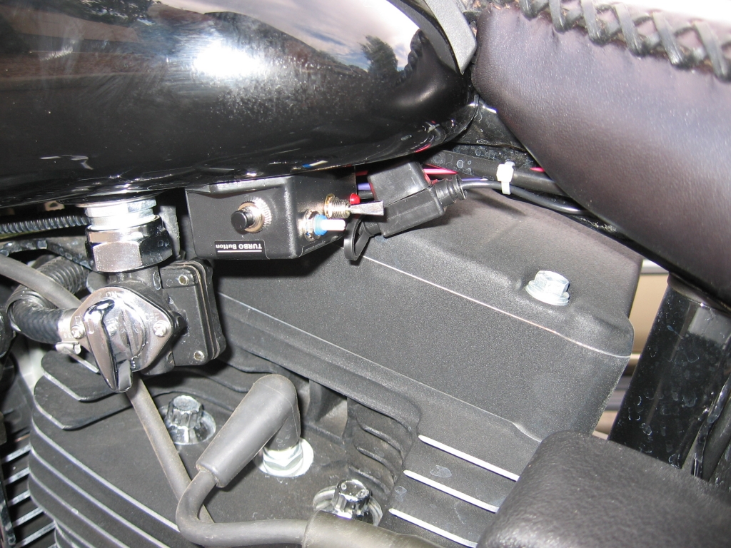
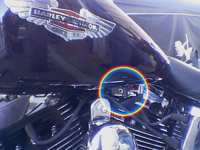
5) – Find the location where you would like to mount the controller box. This should be an easy to reach location where you can turn it on and off. Keep away from any moving parts or direct heat. “Unit is water & shock proof” so try mounting controller box under the gas tank. Once you have identified where you would like to mount the controller box you can then route your wires.
5b)- After wiring is completed then remove the adhesive paper cover on the back of the controller box. Make sure surface is clean for best adhesion and also use cable ties supplied.
VIBERIDER Controller Box and Wiring Explanation Video
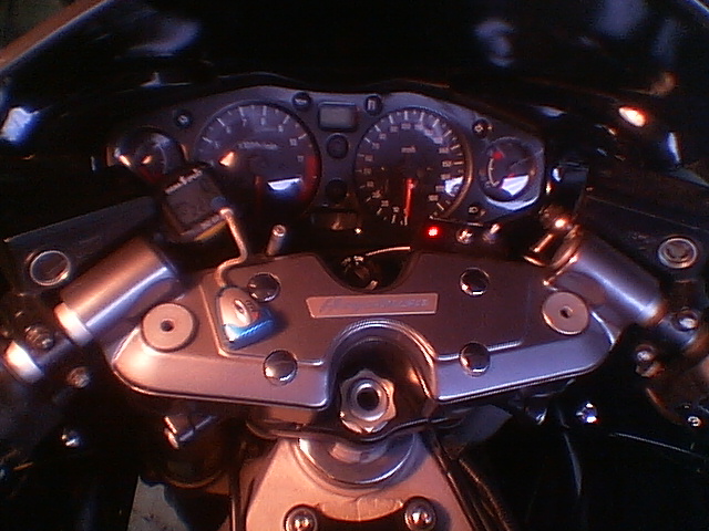
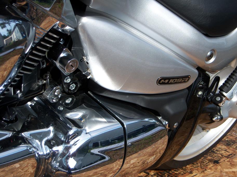
VIBERIDER Controller Box Placement Photos
VIBERIDER Wiring Installation Guide
6) – HARLEYS” PURPLE WIRE TO RPM GAUGE OR NEGATIVE COIL: Route the purple wire to 1 of 4 signals on Harley’s depending on the year model:
Harley’s Made Before 2003 – You can attach the purple wire to the negative side of coil crimp on the spade connector. (not the spark plug wire) If you are not sure which is the negative lead, try one, if incorrect no damage will occur. When testing, if unit fails to operate simultaneously, simply move the wire to the other coil lead.
Alternately this can be connected to a Hot Pink wire the tachometer signal is best. This hot pink wire covered with a black boot about 1” long under the dash on the tank or behind the headlight or in a harness under the seat.
Harley’s Made in 2003 to 2010 electronic ignition- have a blue wire with an orange stripe coming off the coil.
Harley’s Made in 2011 and onwards: Connect the purple wire to the gray wire with blue stripe. These wires runs under the seat on the right side of the battery in one of the harnesses connected to the ECM; use the quick splice connector on the signal wire.
Harley Davidson has yellow/green for common positive, blue/orange for the front cylinder, yellow /blue for the rear cylinder.
6A) – “METRIC/FOREIGN” PURPLE WIRE TO RPM GAUGE OR NEGATIVE COIL: Best way is the tach wire harness near steering fork. “If in despair, check with your local dealer to find out which color wire is for tach and where it can be found.” Most motorcycles will have two wires going to each of the two or four coils. Each coil will share one common color wire and will have one different color wire. Or the common color is positive, and the uncommon colors are negative. You want the negative wire that’s the uncommon color.
Examples:
Yamaha has a red/black wire on both coils- that is positive. The other wire is orange or gray- that is the negative side.
Honda is black/white for positive, blue/yellow and yellow/blue for negative.
Suzuki RPM wire is yellow with blue stripe or has orange/white on both coils as positive, and white or black/yellow as negative.
Kawasaki has red/green for common positive, black or black/green for the negative side. Stick coils are on top of the spark plugs.
For some foreign bikes, it may be easier to splice in to the coil wire.
VIBERIDER Wiring Installation Video

Battery Connections & Seat Quick Disconnector
7) – BATTERY WIRES: (Fuse out of in-line fuse holder.)
Crimp on spade terminal to inline fuse holder and connect to positive (+) battery terminal then route the red wire from controller box to the in-line fuse and connect with supplied heat shrink tubing. The Black wire to negative (-) terminal cut to proper length and crimp on the spade connectors and attach to battery.
8) – SEAT QUICK DISCONNECTOR Make sure the female plug is on the controller box side and the male plug is on the seat vibrator side. 1st put the larger heat shrink on to go over the red & white wires then use smaller ones for red & white wires. Now match the red wire to red wire on controller box and white wire to white wire on controller box and plug. Put fuse in holder and turn the controller box on, the light should go on. Press the “turbo” button to test. This should cause the stimulator to operate at full speed. Turn controller box off. Place the seat back on the motorcycle making sure not to crush wires under seat.
VIBERIDER TESTING
9) – Start bike, turn on controller box. While the bike is idle, put finger on stimulator and turn the synchronizer adjuster knob until there is a minimal pulsation, it is set. Now throttle up to your cruising RPM’s the stimulator should increase hold at that RPM and depress the “turbo” button to assure the stimulator is at full speed. You should feel no change.
10)– After wiring is completed then remove the adhesive paper cover on the back of the controller box. Make sure surface is clean for best adhesion and also use cable ties supplied to attach.